Did Ampere invent the galvanometer, the telegraph, the electromagnet, the electric motor ... ?

By Christine Blondel and Bertrand Wolff
Translation by Andrew Butrica
Numerous dictionary and encyclopedia articles, in print and online, assert that Ampere invented the galvanometer, the first electric telegraph, the electromagnet with Arago, and even the electric motor.
Does it harm a savant’s deserved acclaim—as great as he may be—to examine the thing more closely? For us, it is an opportunity to challenge the rather common tendency to confuse physical laws and technical inventions, as if invention was simply the “application” of a physical law. There is no shortage of inventions, such as the steam engine, that preceded the scientific theories that explain how they work. However, one often tends to attribute to a single man that which belongs to a group within which other savants, manufacturers, inventors, and engineers played a decisive role. For a physical theory to be embodied in not just a laboratory curiosity, but a technical object actually utilized, a whole series of conditions intervene positively or negatively: the technical means available, societal demand, the economic and social context, and invention policy. The telegraph offers an exemplary case study.
Ampere and the history of telegraphy
Ampere’s contribution to the history of the electric telegraph is limited to the following sentence published in his 1820 memoir:
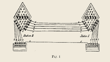
"One could, by means of as many wires and magnetized needles as there are letters, and by placing each letter on a different needle, establish, with the help of a battery placed far from these needles, and which one will make communicate alternately by its two ends to those of each conductor, a sort of telegraph suitable for writing all the details that one would wish to transmit across any obstacle whatsoever. By connecting to the battery a keyboard whose keys carry the same letters and which establish communication by their depression, this means of correspondence could take place with relative facility and would require only the time necessary to touch on the one hand and to read on the other hand each letter."
|
The word telegraph already was well known. The first operational line of the Chappe brothers’ optical telegraph opened between Paris and Lille in 1794. This means of communication, faster than a messenger on horseback, enabled the transmission of military dispatches in a few hours, and subsequently in just a few minutes. A system of semaphores, mounted on towers spaced 15 kilometers (ten miles) apart, was installed throughout France. From one station to the next, employees equipped with telescopes received and retransmitted the signals (without understanding them), at least during days of good weather. Fig. 1. At the Louvre, the heart of the Chappe telegraph network (life drawing by Charles Norry, 1799). In his memoir, Ampere states that he learned from Arago that the principle of his telegraph “had already been proposed by Mr. Soemmering, except that instead of observing the change in direction of magnetic needles, which were not known then, the author proposed observing the decomposition of water in as many vessels as there are letters.” Soemmering’s electrochemical telegraph had been described in the Journal de physique in 1811. It had been demonstrated over a distance of three kilometers (two miles), but this telegraph, like the one proposed by Ampere, could not rival the Chappe telegraph. |
|

The telegraph system proposed by Ampere would have needed even more intense currents than that of Soemmering. Ampere’s proposal actually came in the wake of his experiment showing that the deflection of a needle was the same at all points of a circuit, even at great distances from the battery [See the video L'expérience d'Oersted  ]. He was then interested in understanding the concepts of electric current and intensity, not at all in the transmission of information at a distance, a question to which he never returned in his later writings.
The first operational electric telegraph line, established in 1833 by the German scientists Gauss and Weber, modified Ampere’s idea on several points. The battery was replaced by a generator using the phenomenon of induction discovered in 1831 by Faraday. A coil of wire wrapped around a needle increased the magnetic effect, which enabled the use of weaker currents [See the “multiplier” fig. 5]. In addition, encoding each character as a succession of five signals allowed the use of a single line. Nonetheless, this short-distance telegraph of Gauss and Weber remained in the experimental stage.
|
|
In England, the need to communicate between stations, linked to the development of railways, was at the origin of the first commercial electric telegraph lines in the late 1830s. The system was patented in 1837 by William Cooke and the physicist Charles Wheatstone. Their signal code—shown below—required five wires. Fig. 2. The Cooke and Wheatstone telegraph |
Major innovations were due next to an American painter interested in science, Samuel Morse, who joined with an inventor and mechanic, Alfred Vail, to develop the “Morse system” in 1837.
A first innovation resided in the separation of the transmitter circuit from the receiver circuit, each fed by a generator. In the transmitter circuit, a weak current sufficed to transport the information over great distance. This current flowed through the windings of an electromagnet which controlled the opening and closing of the receiver circuit. This system—a switch in a circuit controlled by a current in a main circuit—is what we today call a relay. The receiver circuit then is a very short circuit in which more intense currents can circulate without any disadvantages. The transmission of information thus was independent of the energy supply necessary for the operation of the receiver system. Another essential innovation concerned the encoding of characters. The encoding was done by a combination of short (dots) and long (dashes) current pulses, the famous Morse code. The operator used a spring lever, the “Morse key,” that allowed one to make or break contact with the generator quickly. |
Fig. 3. Morse receiver: at right the electromagnet and its movable armature (Lycée Guez de Balzac, Angoulême, France) |

Finally, at the receiver, a second electromagnet was substituted for the magnetized needles. It allowed one to etch the dots and dashes corresponding to the transmitted characters on a recording tape.
It was necessary to convince investors, and in 1844 the first interurban line was put into service between Washington and Baltimore. It was Morse’s combination of a simple code and ingenious technical processes, the separation of the transmission of information from the transmission of energy, that was at the heart of the success of the electric telegraph in the entire world beginning in 1845, that is to say 25 years after Ampere’s memoir. In 1850, tens of thousands of kilometers of lines were in service. Initially a technology that assisted the first rail lines, the telegraph did not take long to transform commerce, finance, meteorology, military communications, and the press. During the 1850s, the saga of underwater telegraph cables began ...
The galvanometer
In the case of the invention of the galvanometer, an apparatus for measuring current intensity, we will see physicists and manufacturers contribute at the same time [See the video A la recherche de la mesure du courant ]
|
It is still in his October 1820 Memoir that Ampere wrote: “There was no instrument that would make known the presence of current in a battery or conductor, that would indicate its energy and direction. This instrument exists today; [...] an apparatus similar to a compass, and which differs from it only by the use that one makes of it [...]. I think [that] one should give it the name galvanometer.” Ampere’s device, baptized the galvanometer, was far from enabling a true measure of current intensity, a quantity that at that time he had not yet defined. Besides, this mechanism, a simple magnetized needle placed under a conducting wire, was more aptly called a “galvanoscope” in the memoir manuscript. |
|
|
Fig. 4. The principle of the “galvanoscope.” The wire conductor is oriented in the north-south direction. The action of terrestrial magnetism on the magnetized needle placed at O is represented by Ot. The magnetic action of the current is represented by Oc. When current flows, the needle deviates from its original direction Ot. |

As the video L'expérience d'Oersted shows, it requires a current of strong intensity to deflect a compass needle an appreciable amount. To detect weak electric currents, the German physicist Schweigger initially imagined the multiplier. As its name implies, the goal is to multiply the action of the current by having the wire conductor loop several times around the needle (Fig. 5).
|
|
Fig. 5. The principle of the Schweigger “multiplier.” The current flows from A toward B above the needle and in an opposite direction from C toward D below the needle. From Oersted’s experiment, we know that these two portions of current add their actions on the needle. It is the same for the segments BC and DF. The needle thus is engaged by four actions in the same direction. By wrapping several turns around a rectangular frame suitably insulated, Schweigger obtained a strong multiplier effect. Then in 1825, the Italian physicist Leopoldo Nobili operated Schweigger’s multiplier on the “astatic” system of Ampere—in fact almost astatic—formed by two parallel needles suspended from the same wire and positioned in opposite directions. The terrestrial magnetism acted very feebly on the whole, because it acted only on the weak magnetic difference between the two needles (Fig. 6). Fig. 6. The principle of the Nobili galvanometer. |


|
The multiplier increases the influence of a weak current (Oc in Fig. 1), while the nearly astatic setup strongly decreases the influence of the Earth (Ot in Fig. 4), which makes the instrument very sensitive. In Nobili’s galvanometer, the deflection of the needle increased with the intensity of the current, but there was no simple mathematical relationship between the intensity and the angle of deviation θ. Also, despite its name, the instrument did not measure current intensity. In 1836, the French physicist Pouillet invented the first “absolute” galvanometer, that is to say, it enabled the measurement of current intensity. The magnetized needle was arranged in the center of a circular frame around which was wrapped the wire. If the radius of the circle were sufficiently large compared to the size of the needle, then the tangent of the angle θ (Fig. 4) would be proportional to the current intensity. Fig. 7. Nobili Galvanometer (Manufacturer: Breton Frères, Paris, mid-nineteenth century). |
|

Arago, Ampere, and the magnetization of iron and steel by electricity
In the fall of 1820, shortly after attending the Oersted experiment, Arago published his “Expériences relatives à l'aimantation du fer et de l'acier par l'action du courant voltaïque.”
“The brilliant discovery that Mr. Oersted has just made consists, as we have seen, of the action that the voltaic current exerts on a previously magnetized steel needle. In repeating the experiments of the Danish physicist, I recognized that this same current strongly develops the magnetic quality in the strips of iron or steel, which initially, were totally lacking in that quality. [...] The connecting wire communicates to the soft iron only a momentary magnetization; if one uses small bits of steel, one gives them, sometimes, a permanent magnetization. I have even managed in this way to magnetize completely a sewing needle.”
Arago, having shown Ampere this experiment of magnetizing a steel needle with a rectilinear current, the latter suggested that the magnetization would be stronger if the needle were placed inside a coil carrying current. And, indeed, Arago continued,
“After staying in the coil a few minutes, the steel needle had received a rather strong dose of magnetism; the position of the north and south poles moreover was found to conform perfectly to the result that Mr. Ampere had deduced, in advance, from the direction of the elements of the coil”
Indeed, the value of the experiment for Ampere was its support of his explanation of magnetization in agreement with his hypothesis of currents in magnets [See the page Ampère lays the foundations of electrodynamics]: “The current in each turn [of the coil] brings about a similar one directed in the same direction on the surface of the steel, and consequently in its interior.”
The temporary magnetization of the soft iron, under the action of an electric current, is the physical property at the heart of the functioning of the electromagnet. But, it was of no interest to either Ampere or Arago. In their experiments, besides the abstract questions touching on the theory of magnetization, it was the permanent magnetization of steel, fundamental for the manufacture of marine compasses, that mattered. At the beginning of his memoir, reproduced above, Arago mentioned “blades of iron". However, the experiments that he described involved only blades or needles of steel. For iron, he was content to notice the temporary magnetization of filings.
|
|
It was the public demonstrator, William Sturgeon, who, in 1824, realized the first electromagnet. Formed in the shape of a horseshoe (Fig. 8), it allowed him to lift a mass of 4 kg, that is, 20 times its own weight. But, this again was an object of curiosity.
Fig. 9. Horseshoe demonstration electromagnet [See the video L’électroaimant : un aimant à volonté |
|


Davy, Faraday, Ampere, Barlow: Did they invent the electric motor?
If one could reduce an invention to the discovery of its physical principle, then the candidates for the invention of the electric motor would be numerous. On the other hand, the electric motor, understood as a device that produces useful mechanical energy from electricity, was developed in the second half of the nineteenth century. None of the devices that we are going to talk about can make such a claim.
[See the video Produire du mouvement avec un courant électrique ? ]
In November 1820, the English physicist and chemist Humphry Davy commented about Oersted’s recent discovery:
“As bodies magnetized by electricity [a wire carrying the current] put a needle in motion, it was natural to infer that a magnet would put bodies magnetized by electricity in motion: this I found was the case.” For Davy, as for Biot, if a current acted on a magnetized needle, it was because the conducting wire underwent, during the passage of the current, a temporary magnetization. "...Some pieces of wire of platinum, silver, and copper, were placed separately upon two knife edges of platinum connected with two ends of a powerful voltaic battery, and a magnet presented to them; they were all made to roll along the knife edges.”
|
|
This experiment is not far from the experiment known as the “ Laplace's rail” that became a great classic in twentieth-century instruction. Why the "Laplace's” rail? Because the force acting on the piece rolling on the rails was known, at least in France, as the “Laplace force”. This experiment shows that with an electric current, one can create movement or, in modern terms, one can convert electrical energy into mechanical energy. Is that not the definition of an electric motor? However, Davy did not envisage any practical application for his laboratory device in which some see the prototype of the linear electric motor used on certain train lines or the electromagnetic railgun. Fig. 10. When the current is established in the circuit formed by the rails and the rod, the latter is set in motion either to the left or the right depending on the direction of the current. |

|
In September 1821, Faraday announced that he had obtained the rotation of a conductor carrying a current under the action of a magnet and vice versa. Shortly afterward, Ampere added the rotation of a mobile circuit under the action of another circuit. [See the page Faraday, Ampere, and the mystery of continuous rotations]. Circuits in continuous rotation as a result of a magnetic field: is that not the principle of electric motors today? Nevertheless, when the correspondence between Ampere and Faraday was in full swing, the debate was far from dealing with the use of electromagnetic force to produce mechanical work! Their laboratory experiments, whose performance was compromised by friction and which needed high currents, were far from being capable of providing the least amount of useful work. For both of them, the value of these experiments lay in their theoretical implications. Fig. 11. In this Ampère table, as modified by Pierre-Augustin Bertin, a conductive coil surrounds a copper reservoir. One fills the reservoir with acidulated water, and current flows in the moveable circuit in the form of a portico. When the coil carries a current, it creates a magnetic field that acts on the moveable circuit, and the portico starts to rotate around the central column. (Lycée Bertran-de-Born, Périgueux, France). |
Francis Gires ASEISTE |

Throughout the nineteenth century and later, manufacturers’ catalogs of instruments for high school (lycées) offered numerous variations on these “continuous rotations”. When a new heading, “electric motor”, appeared in these catalogs at the beginning of the twentieth century, no link was made back to these continuous rotations, which shows that they still were regarded as experiments tied to the theory of electromagnetism.
|
|
In March 1822, Peter Barlow carried out a “curious electromagnetic experiment”. He situated his experiment in the persistent questions raised by the discovery of continuous rotations by Faraday: “I am not aware that the following electro-magnetic experiment will throw any additional light upon the very interesting results of Mr. Faraday”. This time, it was a metallic toothed wheel that “will immediately begin to rotate with an astonishing velocity, far beyond the power of the eye to follow.” Since then, the experiment of “Barlow’s wheel” also became a great classic. Fig. 12. Barlow’s wheel as shown in the author’s original drawing. |

More so than the devices of Ampere or Faraday, Barlow’s wheel is often shown in textbooks and educational sites as being “the first electric motor”, sometimes referred to as “Barlow’s motor”. However, like Faraday and Ampere, Barlow intended to illustrate the properties of the electromagnetic force, not to put forth a technical application. The first electric motors powered by batteries used the attraction between a magnet (or an electromagnet) and a coil, and not the continuous rotations of Ampere and Faraday or the electromagnetic force demonstrated in Barlow’s wheel. In addition, these early engines built during the period 1840-1870 had no future. Powered by batteries, their operating costs remained too high compared to the cost of a steam or gas engine. [See the page Les usages variés, mais limités, de l'électricité avant la dynamo et les usines électriques ] ].
From physics experiment to technical object
The examples discussed here briefly—the electromagnet, the electric motor, the galvanometer—suggest, as in the case of the telegraph, that technical objects are most often the result of a constellation of various ideas, experiments, and tests implemented by people with different backgrounds. In addition, the process takes place over a more or less long period. It is impossible to assign a single name, a single date, or a single place to these inventions!
A bibliography of “secondary sources” about the history of electricity